

A circuit board can look flawless on the bench and still fail after months of heat, vibration, or electrical stress. Often, the weakness is not dramatic. It may be a capacitor operating too close to its temperature limit, or a connector exposed to repeated movement. Small choices matter.
The stakes are growing as electronics become more complex. McKinsey’s 2022 report, “The semiconductor decade,” projected that global semiconductor-industry revenue could reach $1 trillion by 2030, reflecting rising demand across many sectors. That forecast is not a guarantee of supply or product quality. It does underline why designers and buyers need to assess parts carefully, rather than choosing only by price or availability. Circuit Board Components should be judged against the real conditions they will face: operating temperature, current, voltage, vibration, expected service life, and the limits of the surrounding board.
Start with the datasheet. Check ratings, package details, and qualification information, then verify that the selected part suits the assembled product—not just the schematic. Look closely at thermal margins. A component that barely meets its rating may leave little room for hot enclosures or changing loads. Proven sourcing matters, too; traceability can help teams investigate failures and manage substitutions. No checklist removes all risk. And a datasheet cannot predict every field condition. These seven practical tips offer a disciplined starting point for selecting components that are more likely to last—and for questioning assumptions before they become costly rework.
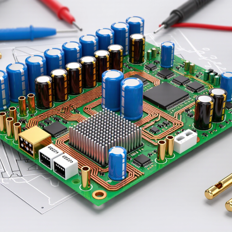
Before choosing components, describe the board’s real working environment. Record the normal and peak temperatures, humidity, vibration, dust exposure, and expected operating hours. A board inside a sealed outdoor enclosure faces different stresses from one in a clean office. Heat matters. Measure temperatures near power devices, not only at the room thermostat.
Check how electrical conditions change during use. Supply voltage may dip at startup, while motors or switching loads can create brief surges. Select capacitors, resistors, and semiconductor devices with suitable ratings and practical margin above measured peaks. A rating that barely matches a laboratory estimate may leave little room for aging or measurement error. Review the datasheet’s temperature and voltage derating guidance, and confirm that the chosen package can shed heat on the actual copper layout.
Consider the board’s physical life, too. Equipment mounted near a pump may experience repeated vibration, and connectors can loosen over time. In humid locations, condensation can matter more than average humidity. Small details count. Test a prototype under realistic conditions, including warm-up, load changes, and repeated power cycles. If results differ from your assumptions, revisit the measurements rather than blaming the component immediately. I have seen a “safe” temperature estimate miss a hot spot by several degrees; that is an easy mistake to make. Keep records of the test setup, sensor placement, and operating limits so later design changes can be assessed reliably.

A component’s printed rating is a limit, not a comfortable target. Match voltage ratings to the highest expected voltage, including startup surges and switching spikes. For a capacitor on a 12-volt rail, a 16-volt rating may leave little room for variation. Check the circuit’s actual conditions and the component datasheet before deciding. Small margins can become problems.
Current ratings deserve the same care. A resistor carrying more power than it can shed may discolor the board or fail early. Estimate its dissipation, then allow headroom for enclosure temperature and restricted airflow. Heat builds quietly. Semiconductor ratings also depend on how well heat travels through the package, copper traces, and board. A device rated for a certain current in ideal test conditions may handle less inside a warm, crowded enclosure. Read the derating curves, not just the headline number. For thermal checks, measure a working prototype near the hottest operating point; a room-temperature test can mislead. I have seen a design pass its bench test, then run hotter after installation. That result calls for another review, not a bigger guess.
A circuit board component can look sturdy and still fail after months of heat, vibration, or moisture. Check the specified operating temperature, not just the storage range. A capacitor near a warm power device may need a higher temperature rating than one elsewhere on the board. Leave a margin where practical; running parts at their limits can shorten service life.
Materials matter. Look for clear information about insulation, plating, solderability, and resistance to corrosion. Construction matters too. Inspect lead attachment, package sealing, and whether the component suits the board’s mounting method. For equipment exposed to vibration, a heavy part with long leads may need extra mechanical support. Small details matter. A clean datasheet helps, but it cannot show every weakness in a real assembly.
Consider the actual environment, not an ideal laboratory. Dust, condensation, repeated temperature swings, and nearby chemicals can affect performance. Protective coatings may help, yet they can also trap heat or complicate repair. Test representative boards under realistic conditions, including thermal cycling and vibration when those risks apply. Record failures and revise the design. Honestly, no rating guarantees a long life; even careful choices can miss an unusual stress point.
| Tip | Selection Focus | What to Check | Why It Matters | Practical Design Check |
|---|---|---|---|---|
| 1 | Operating temperature | Compare the component’s rated operating-temperature range with the board’s expected ambient temperature and self-heating. | Operation outside the specified range can accelerate degradation or cause malfunction. | Include enclosure conditions, nearby heat sources, and thermal rise in the temperature estimate. |
| 2 | Component materials | Review materials for the intended environment, including insulation, seals, plating, and exposed metals. | Heat, moisture, chemicals, or dissimilar metals can contribute to corrosion, swelling, or insulation failure. | Check material compatibility with cleaning agents, process residues, and expected contaminants. |
| 3 | Mechanical construction | Assess package robustness, lead or termination design, mounting method, and resistance to vibration and shock. | Mechanical stress can crack solder joints, damage terminations, or loosen components. | Use suitable support and strain relief for heavy parts and connectors; consider vibration testing where needed. |
| 4 | Electrical derating | Compare expected voltage, current, power, and ripple with the component’s rated limits. | Operating close to maximum ratings can increase temperature and reduce reliability margin. | Apply design-specific derating guidelines and verify worst-case conditions, not just typical operation. |
| 5 | Moisture and corrosion resistance | Check humidity limits, moisture sensitivity, corrosion protection, and suitability for condensation risk. | Moisture can promote corrosion, leakage currents, and degradation of materials or connections. | Evaluate enclosure sealing, conformal coating, board spacing, and storage or handling requirements. |
| 6 | Thermal cycling and solder joints | Consider package size, coefficient-of-thermal-expansion differences, solder-joint design, and expected temperature cycles. | Repeated expansion and contraction can fatigue solder joints and board connections. | Review land patterns and assembly process; validate designs exposed to frequent or wide temperature swings. |
| 7 | Documentation and traceability | Verify that datasheets, ratings, material declarations, and lot or date-code information are available and consistent. | Clear documentation helps confirm suitability, manage substitutions, and investigate failures. | Record approved specifications and requalify replacements when materials, package, or ratings change. |
A component can meet its voltage rating and still fail in a real board. Check its operating range against the circuit’s actual conditions, including startup surges, heat, and vibration. Compare package dimensions with the footprint and nearby parts. A few tenths of a millimeter can complicate assembly. Review tolerance, power dissipation, and thermal resistance, too. On a warm test board, measure temperatures rather than relying only on typical values.
Availability matters after the prototype works. Check whether the part is stocked through more than one channel and whether its production status is stable. Ask about expected lead times and planned product changes. Keep a qualified alternative on file, but verify its pinout and electrical behavior before approving it. Substitutes are not always interchangeable. Manufacturer support can reveal details that a short datasheet misses, such as recommended soldering profiles or derating guidance. Look for clear technical documents and responsive answers to specific questions. If support is slow, that may be manageable for a low-risk part, but less so in a safety-critical design. It is easy to focus on the schematic and overlook the supply chain. That gap deserves a second look.
A practical 1–5 checklist for evaluating component-selection criteria. Higher scores indicate greater importance to verify during design and sourcing; scores are guidance, not measured failure-rate data.
Check electrical and footprint compatibility first, then confirm operating limits, lifecycle status, availability, and manufacturer documentation and support before committing a design.
A component’s datasheet is a starting point, not proof that it will survive on your board. Check operating temperature, voltage derating, package size, and soldering limits against real measurements. Then test representative assemblies, not just loose parts. JEDEC JESD22-A104 describes temperature-cycling methods for assessing component reliability; choose cycle limits and counts that reflect the product’s actual environment. A board near a warm motor needs a different profile from one inside a climate-controlled room. Details matter.
Review the results with the design and quality teams. Track failures, resistance changes, and visible solder-joint cracks, and record the test conditions so another engineer can reproduce them. IPC-9701A provides methods for evaluating surface-mount solder-attachment reliability, including temperature cycling. Use the relevant method as a reference, while checking that its setup matches your board materials and use case. Look closely at borderline results. They may be telling you something. A small shift in resistance can be easy to dismiss, but it may point to a weak connection or an unsuitable component rating. Testing takes time, and not every early test catches long-term wear. Review the evidence, revise the selection when needed, and keep the reasoning documented.
QUICK LINKS
CONTACT US
Office: (+86) 755 23040566
Tel: (+86) 158 9965 5195
E-mail: sale@pcbledmodule.com
Skype: Hans@Rocket-PCB
Whatsapp: 86 1589965 5195
Office Address: 2207,Bid 4,He Gu Shan Hui Cheng,35#,Guang Tian RoYanluo street, Song Gang Town,518105 SHENZHENG, CHINA
Plant ADD.: No 69, Lianfeng North Road, Xianxi Area, ChangAn Town, Dongguan, China.


Copyright © 2025 Rocket PCB Solution Ltd. | All Rights Reserved Sitemap Friendship link: CNC machining heat sink