

loading

BLOG

What Is a Vibration Measurement Meter and How Does It Work?

A Vibration Measurement Meter turns invisible machine movement into readable evidence. It captures acceleration, velocity, or displacement, then displays amplitude across selected frequencies. A technician can place its sensor near a motor bearing and notice a sharp peak before noise becomes a costly failure. The instrument is small, but its decision value can be considerable.

Industry demand reflects this practical role. Grand View Research estimated the global vibration monitoring market at approximately USD 1.56 billion in 2023, with continued growth expected through 2030. MarketsandMarkets also projects strong expansion, although published estimates differ because companies define “monitoring” differently. That disagreement matters. Market numbers are useful signals, not perfect measurements.

Vibration specialist Jason Tranter has emphasized, “The best vibration analysts are not necessarily the ones who know the most about vibration; they are the ones who know the most about machinery.” This principle explains why a Vibration Measurement Meter cannot replace experience. A reading of 7 mm/s may suggest concern, yet machine type, speed, mounting, load, and baseline history change its meaning. Context matters more than a dramatic number.

This article examines how the meter works, including sensors, signal processing, frequency analysis, calibration, and field limitations. It also considers ISO 20816 guidance for evaluating machine vibration. A meter can reveal a failing bearing. It can also mislead. Poor sensor contact, incorrect settings, or rushed interpretation may produce confident but weak conclusions. Reliable measurement requires disciplined technique, traceable data, and careful human judgment.
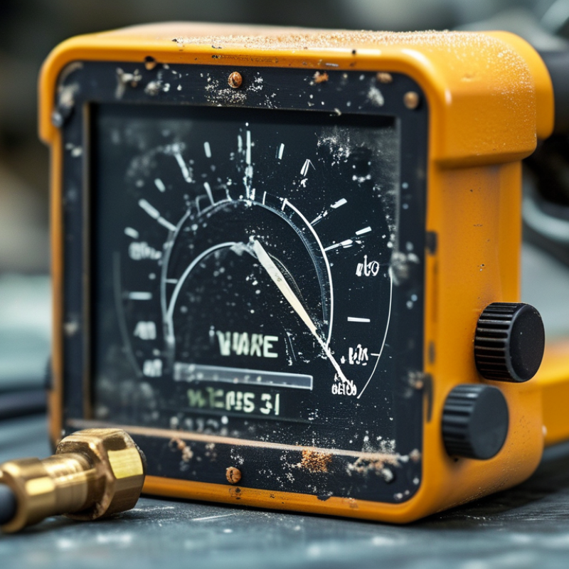
What Is a Vibration Measurement Meter and How Does It Work?

Definition and Purpose of a Vibration Measurement Meter

A vibration measurement meter is an instrument that detects mechanical movement in equipment. It commonly uses an accelerometer to sense changes in acceleration. Some meters also calculate vibration velocity or displacement. The readings may show RMS values, peak levels, and frequency patterns. These measurements help describe how strongly a machine is vibrating. Small changes matter. The main purpose is to identify unusual movement before it develops into serious damage.

In practical maintenance work, technicians use the meter on motors, pumps, fans, gearboxes, and bearings. A sensor is placed firmly on a clean, solid surface. Loose contact can create misleading results. The technician compares the current reading with a reliable baseline from normal operation. A rising value may suggest imbalance, misalignment, looseness, or bearing wear. However, vibration data alone does not prove one exact fault. Temperature, load, speed, and installation conditions can change the result.

A good meter supports condition-based maintenance. It helps teams decide when inspection or repair is justified, rather than relying only on noise or touch. Frequency analysis can reveal repeating patterns that a simple overall reading may hide. Still, the instrument requires regular calibration and consistent measuring points. I would not treat one unexpected reading as a final diagnosis. Repeating the test is often wiser. Even experienced users can overlook a loose mounting bolt or a temporary process change.

Core Components and Sensing Technologies

What Is a Vibration Measurement Meter and How Does It Work?

A vibration measurement meter converts mechanical movement into readable data. Its sensing element detects motion on a machine housing, bearing, or rotating shaft. The sensor then sends a small electrical signal to the conditioning circuit. This stage filters noise and strengthens weak signals. An analog-to-digital converter changes the signal into numerical samples. A processor calculates values such as acceleration, velocity, displacement, RMS, and peak vibration. The display presents results in practical units, while internal memory may store readings for later comparison.

Core Components and Sensing Technologies

Piezoelectric accelerometers respond quickly to high-frequency vibration. They are useful for detecting bearing and gear problems. MEMS capacitive sensors are compact, affordable, and suitable for portable meters. However, they can show more noise in demanding environments. Velocity sensors focus on vibration energy across common machine frequencies. Some systems also use displacement sensing for slower shaft movement. Sensor mounting matters greatly. A loose magnet or dirty surface can distort the reading. A stable connection is not a minor detail.

Tips: Check the sensor cable before testing. Measure at the same point each time. Record machine speed, load, and temperature. Compare readings with earlier data, not one number alone. A clean result can still mislead when operating conditions change. Calibration should follow the manufacturer’s stated interval and a traceable reference. Even experienced technicians can overlook mounting direction. That small mistake deserves attention.

What Is a Vibration Measurement Meter and How Does It Work?

This waveform represents an accelerometer response to a 30 Hz sinusoidal vibration with a 0.25 mm peak displacement. The acceleration peak is approximately 8.9 m/s², calculated from a = (2πf)²x.

How Vibration Signals Are Collected and Processed

A vibration measurement meter turns machine movement into usable evidence.

It normally uses an accelerometer fixed near a bearing, gearbox, or motor housing. The sensor detects tiny changes in acceleration, measured in metres per second squared or g.

The signal travels through a cable or wireless connection into the meter. The instrument first removes unwanted electrical noise. An anti-aliasing filter protects the data before sampling begins.

Sampling rate matters. It must capture the machine’s highest meaningful frequency, not merely produce a large file. The meter then calculates values such as RMS velocity, peak acceleration, crest factor, and peak-to-peak displacement.

Each value shows a different condition.

RMS velocity can indicate overall machine severity.

Crest factor may reveal sharp impacts from a damaged bearing.

Frequency processing adds another layer. The meter converts time-waveform data into a frequency spectrum, commonly through a Fast Fourier Transform. Analysts can then compare peaks with running speed, bearing frequencies, or gear-mesh frequencies.

ISO 13373-1 describes this measurement and analysis approach for machine condition monitoring.

In practice, sensor placement changes the result. A loose magnet can soften high-frequency impacts.

The numbers are useful, but not perfect. Temperature, load, mounting pressure, and operator technique can distort them.

The U.S. Department of Energy’s Operations and Maintenance Best Practices guide reports potential maintenance-cost reductions of 25–30% through predictive maintenance, with downtime reductions of 35–45%.

Those figures are broad estimates, not guarantees. A reliable decision still needs repeated readings, consistent locations, operating context, and an experienced interpretation.

Sometimes, the machine sounds normal. The spectrum disagrees.

Key Measurement Parameters and Reading Methods

A vibration measurement meter detects machine movement and converts it into readable electrical signals. It usually reports acceleration, velocity, or displacement. Acceleration is useful for detecting impacts and high-frequency defects. Velocity often helps assess overall machine condition. Displacement shows larger, slower movement. Read the unit carefully. RMS indicates the typical vibration energy over time. Peak shows the highest instant value, while peak-to-peak measures the full movement range. Frequency, shown in hertz, can connect a vibration pattern with shaft speed, looseness, or imbalance. A motor housing may feel smooth, yet its meter reading can reveal a sharp frequency peak.

For a reliable reading, place the sensor firmly on a clean, rigid surface. Keep the position and direction consistent. Measure near the bearing, then record the operating speed, load, temperature, and measurement point. A time waveform shows vibration changes moment by moment. An FFT spectrum separates those changes by frequency, making repeated peaks easier to examine. Look for harmonics, sidebands, or sudden increases from the established baseline. Do not judge equipment from one number alone. Readings can shift because of sensor pressure, mounting quality, or changing process conditions. I have seen a loose hand-held contact create an unusually high value. That small error can lead to the wrong maintenance decision. Even a careful measurement is not perfect, so repeat unusual results before interpreting them.

Common Applications and Selection Considerations

What Is a Vibration Measurement Meter and How Does It Work?

A vibration measurement meter detects movement in rotating or reciprocating equipment. Its accelerometer converts mechanical motion into an electrical signal. The instrument then displays acceleration, velocity, displacement, or frequency. Many models also use FFT analysis to identify imbalance, looseness, misalignment, and bearing damage.

Common Applications and Selection Considerations

Maintenance teams use these meters on motors, pumps, fans, compressors, gearboxes, and production lines. A practical inspection often begins at the bearing housing, where vibration travels into the machine frame. ISO 20816-1:2016 recommends evaluating machine vibration through measurements on non-rotating parts. However, limits vary by machine type, speed, mounting, and operating condition. One number cannot explain everything.

The U.S. Department of Energy’s Operations & Maintenance Best Practices Guide reports that predictive maintenance may reduce costs by 8–12% compared with preventive maintenance, and by 30–40% compared with reactive maintenance. These figures are useful, but field results depend on training, sampling consistency, and accurate diagnosis. A meter with high frequency range suits bearing analysis. A simpler velocity meter may be enough for routine motor checks. Wireless logging helps with repeated routes, while a handheld unit supports quick troubleshooting.

Tips: Record speed, load, temperature, and measurement location. Compare readings with the machine’s history, not only a generic alarm value. Calibrate the sensor regularly. A single reading can mislead. That is easy to forget.

Chat Online
Chat Online
Leave Your Message inputting...
Thank you for your attention. Please kindly describe your question first, or please send your inquiry to our email sale@pcbledmodule.com, and we will reply to you ASAP. Welcome, what can I help you?
Sign in with: