
English


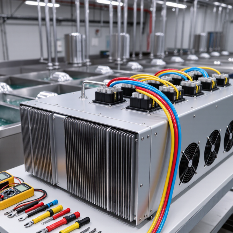
A Phase Lack Chrome Rectifier is a specialized power unit used in chrome electroplating systems. It converts incoming alternating current into controlled direct current for the plating bath. The equipment regulates voltage, amperage, and current stability during chrome deposition. Without that control, the coating may appear dull, uneven, brittle, or poorly bonded.
The phrase “phase lack” usually describes phase loss or phase imbalance in a three-phase electrical supply. This fault can make the rectifier run hotter than expected. It may also create unstable output, louder transformer noise, and irregular chrome thickness across a large workpiece. Small details matter. Cable condition matters. Cooling airflow matters. Bath temperature matters too.
Electroplating engineer Dr. Robert A. Pinner wrote, “Good plating depends on controlling the whole system, not merely the current.” That principle remains practical for modern chrome lines. A rectifier can be powerful, yet still perform poorly when sensors, connections, or maintenance routines are neglected. This is where many explanations become too simple.
A proper evaluation should check input phases, output ripple, cooling fans, fuses, busbars, and measured current. Use calibrated instruments. Follow the manufacturer’s electrical procedures. Never rely only on a display reading. A damaged phase monitor may hide a developing failure.
This guide explains what a Phase Lack Chrome Rectifier does, why phase problems affect chrome quality, and which operating signs deserve attention. The terminology can be confusing. The equipment is not. It is a controlled power source at the center of a demanding surface-finishing process.
What Is a Phase-Loss Chrome Rectifier?
A phase-loss chrome rectifier is a chrome-plating power unit operating with one missing AC phase. It is not a special rectifier designed for phase loss. The term usually describes a fault condition in a three-phase rectifier system. Inside the unit, diodes or thyristors convert incoming AC power into controlled DC current. This current moves through the plating bath and deposits chromium onto a prepared metal surface.
The warning signs can appear quickly. Output current may fall, pulse, or become unstable. The workpiece may show dull areas, uneven thickness, or poor coverage around edges. Cabinet cooling fans can sound strained. Input cables and transformers may also become unusually warm. A phase-loss fault often increases ripple, stresses rectifier components, and may trigger protective shutdowns. Do not judge the problem from the coating alone. Measure all incoming phase voltages and inspect fuses, terminals, contactors, and control signals with suitable test equipment.
The wording can be confusing. Some technicians call it a “phase lack” rectifier, but “phase loss” is clearer engineering language. A loose terminal may imitate a failed rectifier. That assumption can waste time. In my experience, recording voltage, current, bath temperature, and coating appearance together gives a more reliable diagnosis. The plating process also matters. Poor solution control or weak electrical connections can create similar defects, so the rectifier should be checked alongside the bath and anode arrangement.
QUICK LINKS
CONTACT US
Office: (+86) 755 23040566
Tel: (+86) 158 9965 5195
E-mail: sale@pcbledmodule.com
Skype: Hans@Rocket-PCB
Whatsapp: 86 1589965 5195
Office Address: 2207,Bid 4,He Gu Shan Hui Cheng,35#,Guang Tian RoYanluo street, Song Gang Town,518105 SHENZHENG, CHINA
Plant ADD.: No 69, Lianfeng North Road, Xianxi Area, ChangAn Town, Dongguan, China.


Copyright © 2025 Rocket PCB Solution Ltd. | All Rights Reserved Sitemap Friendship link: CNC machining heat sink